
plotmaster 9000
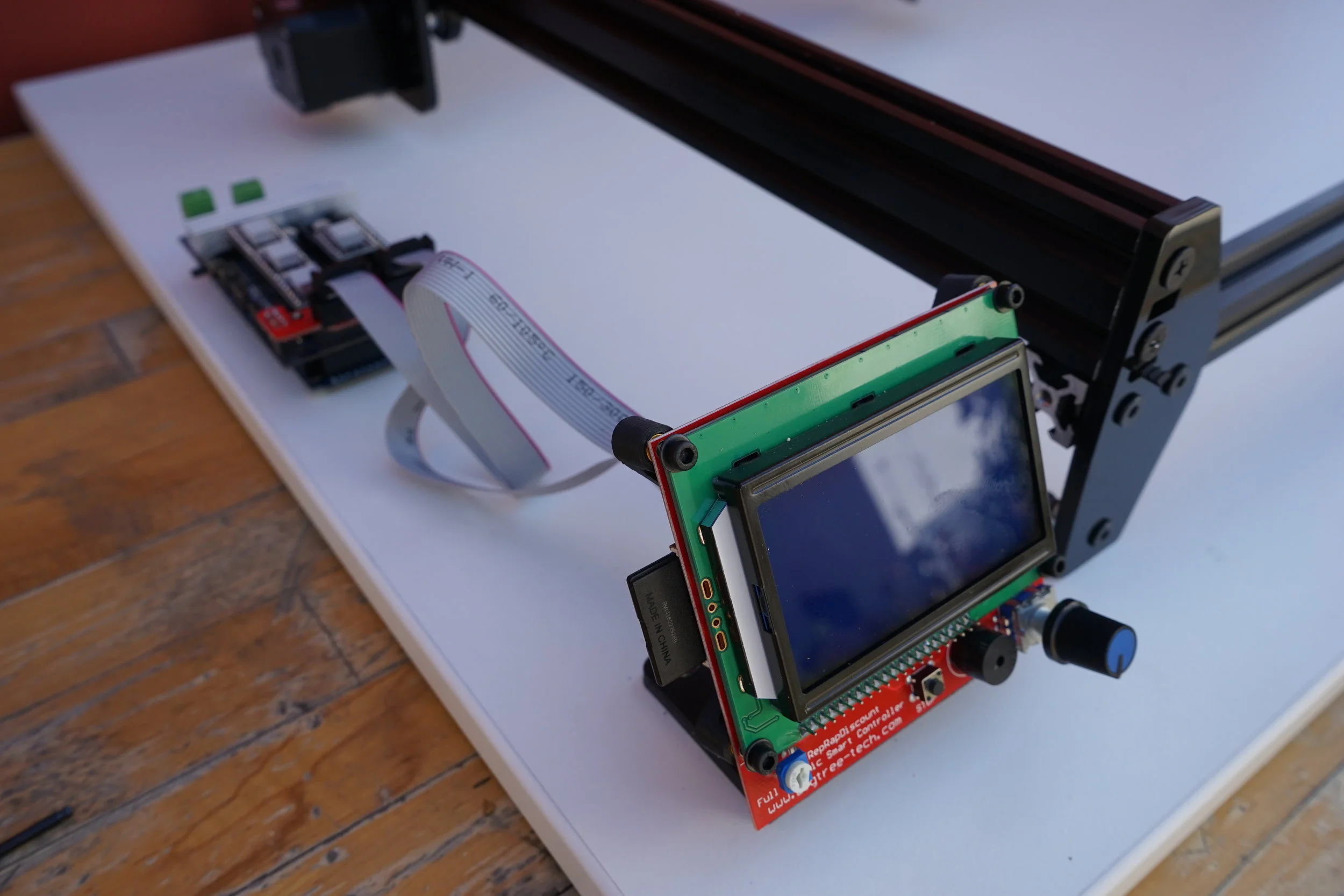
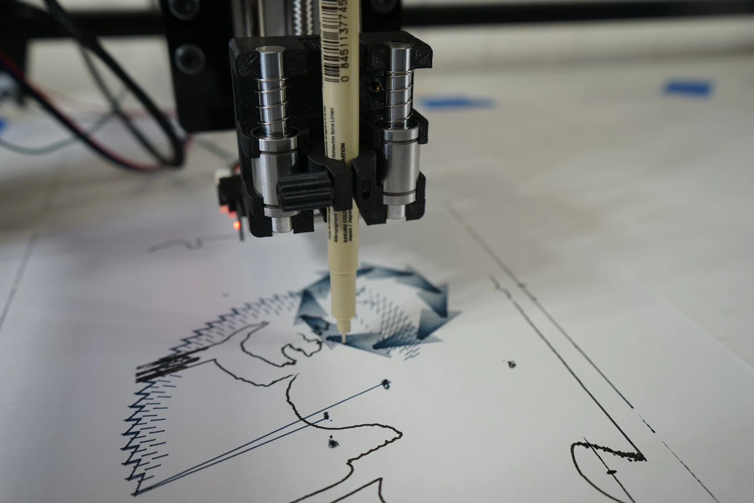
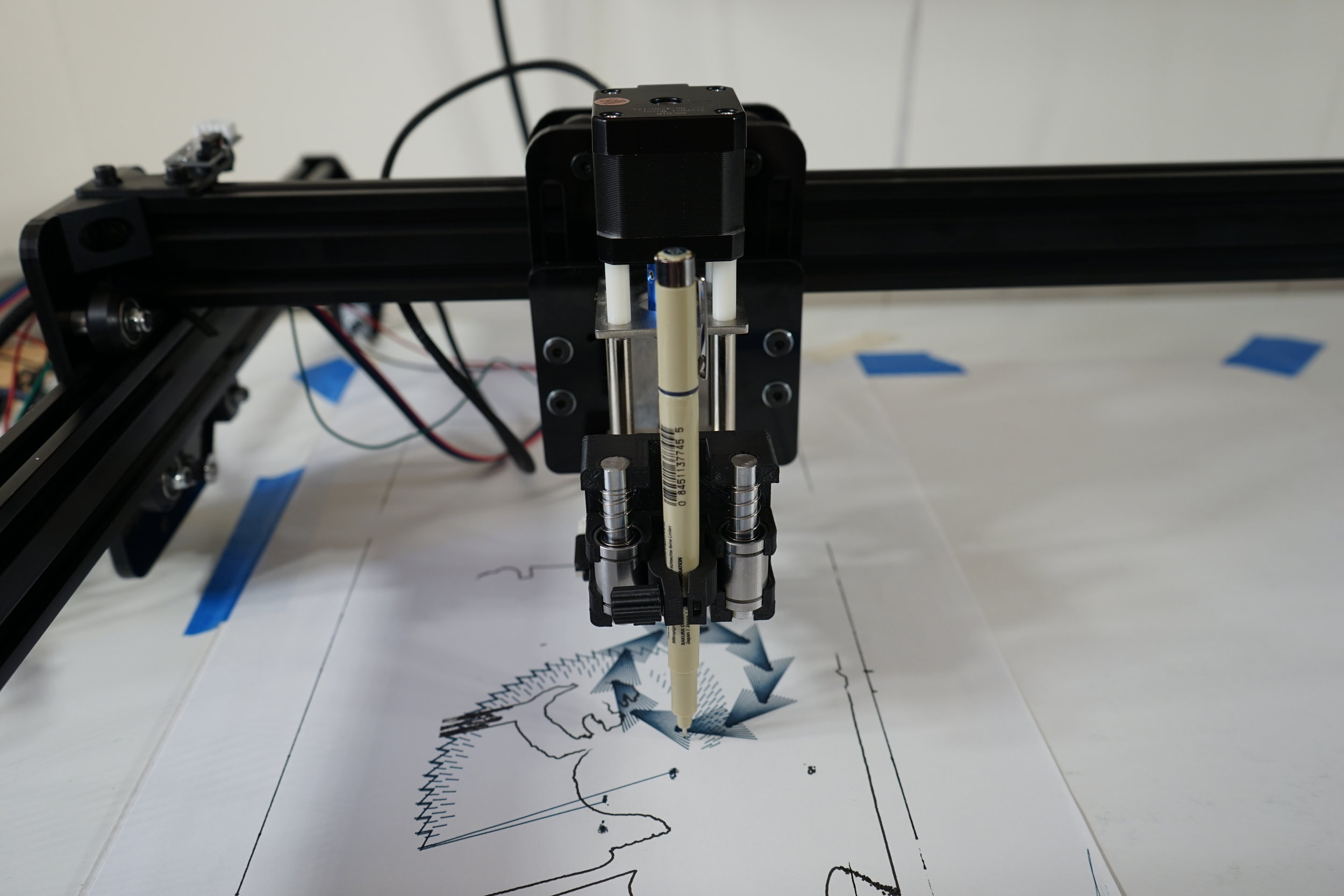
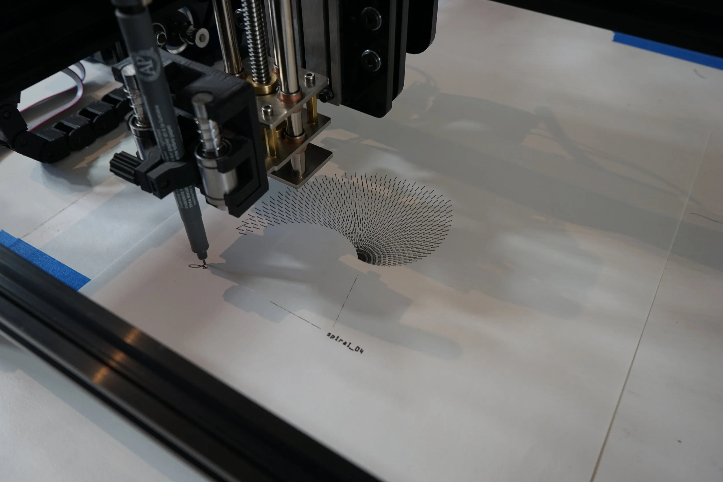
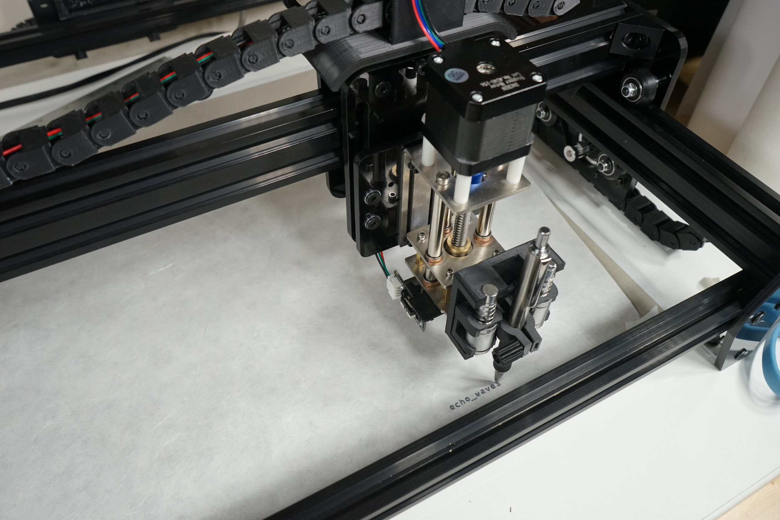
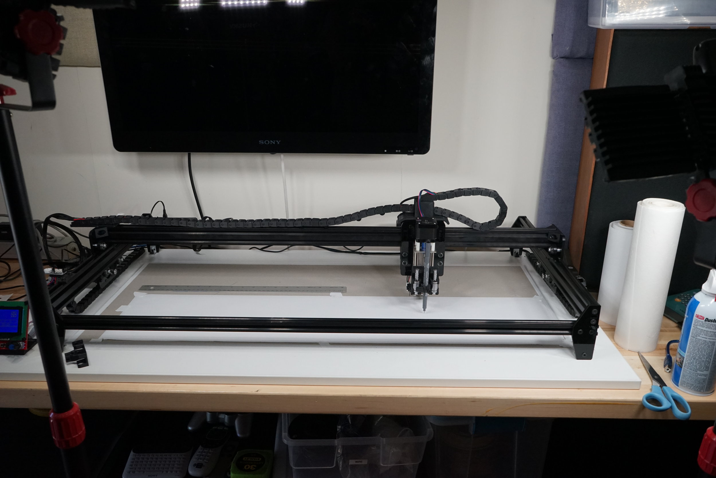
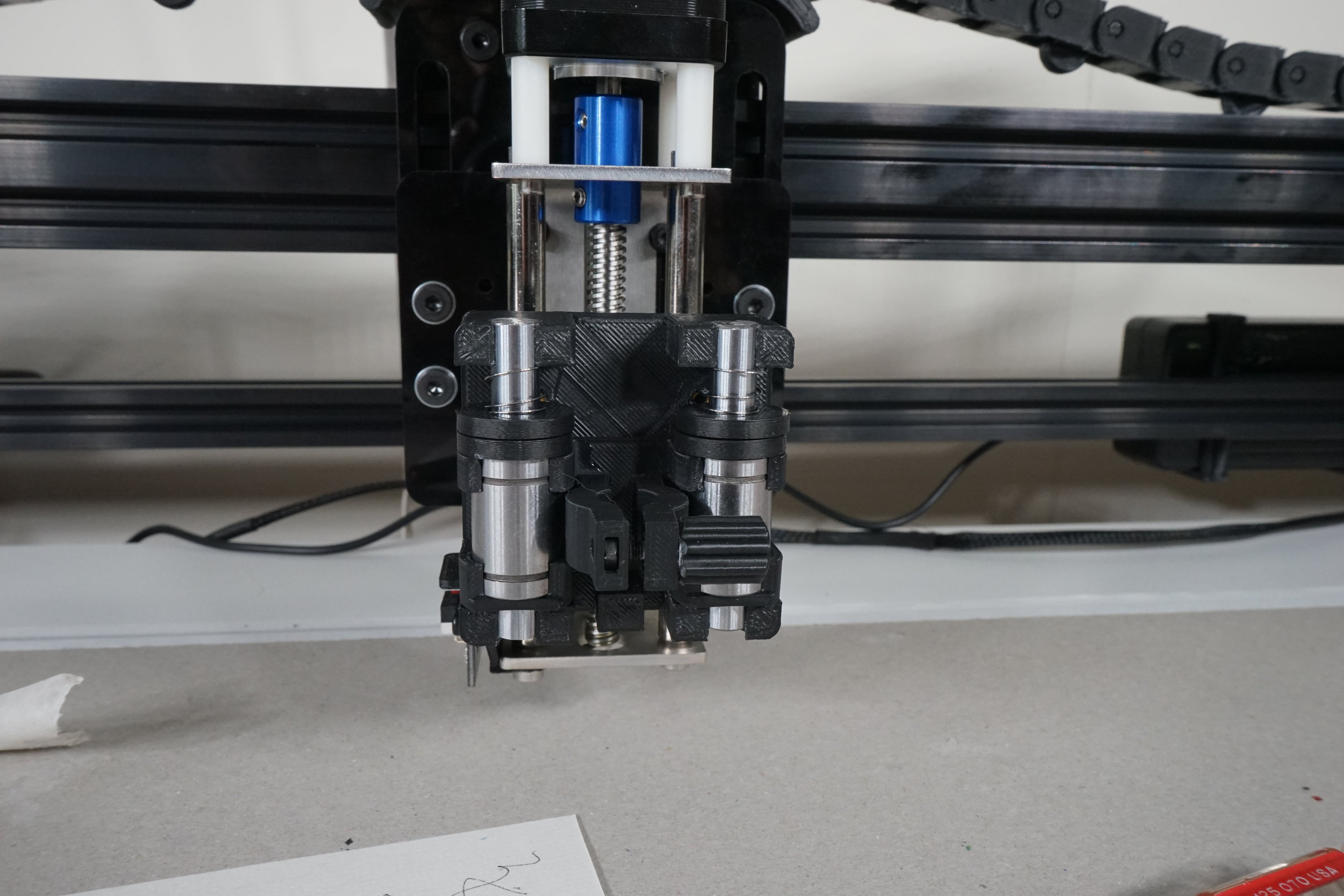
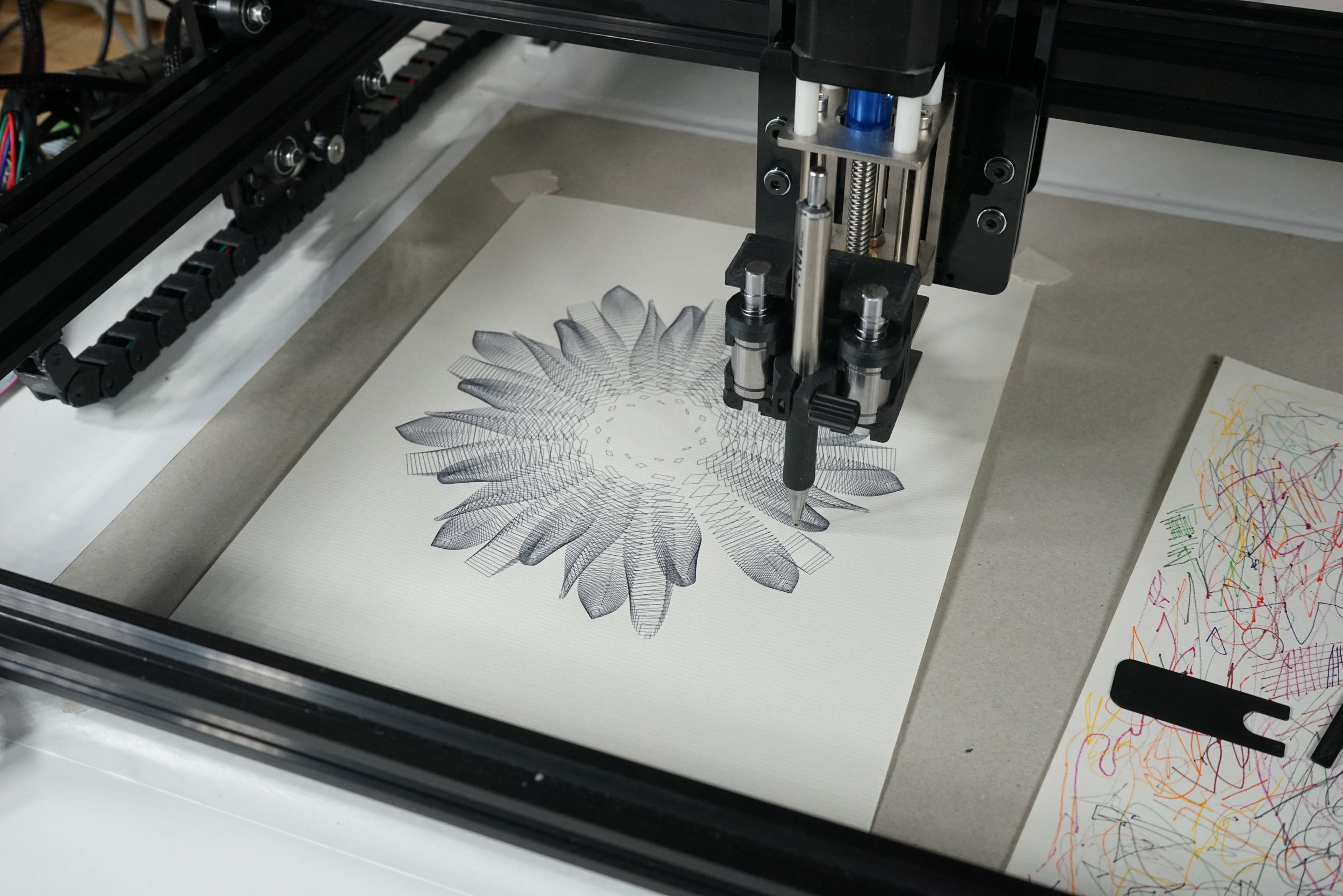
building the plotmaster 9000
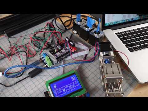
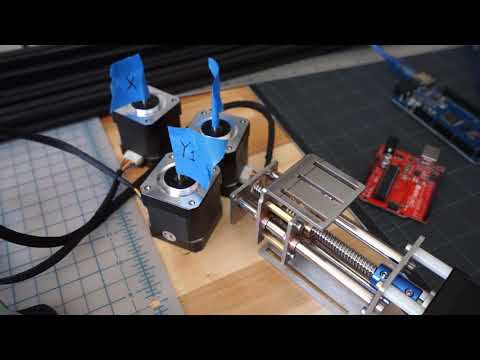
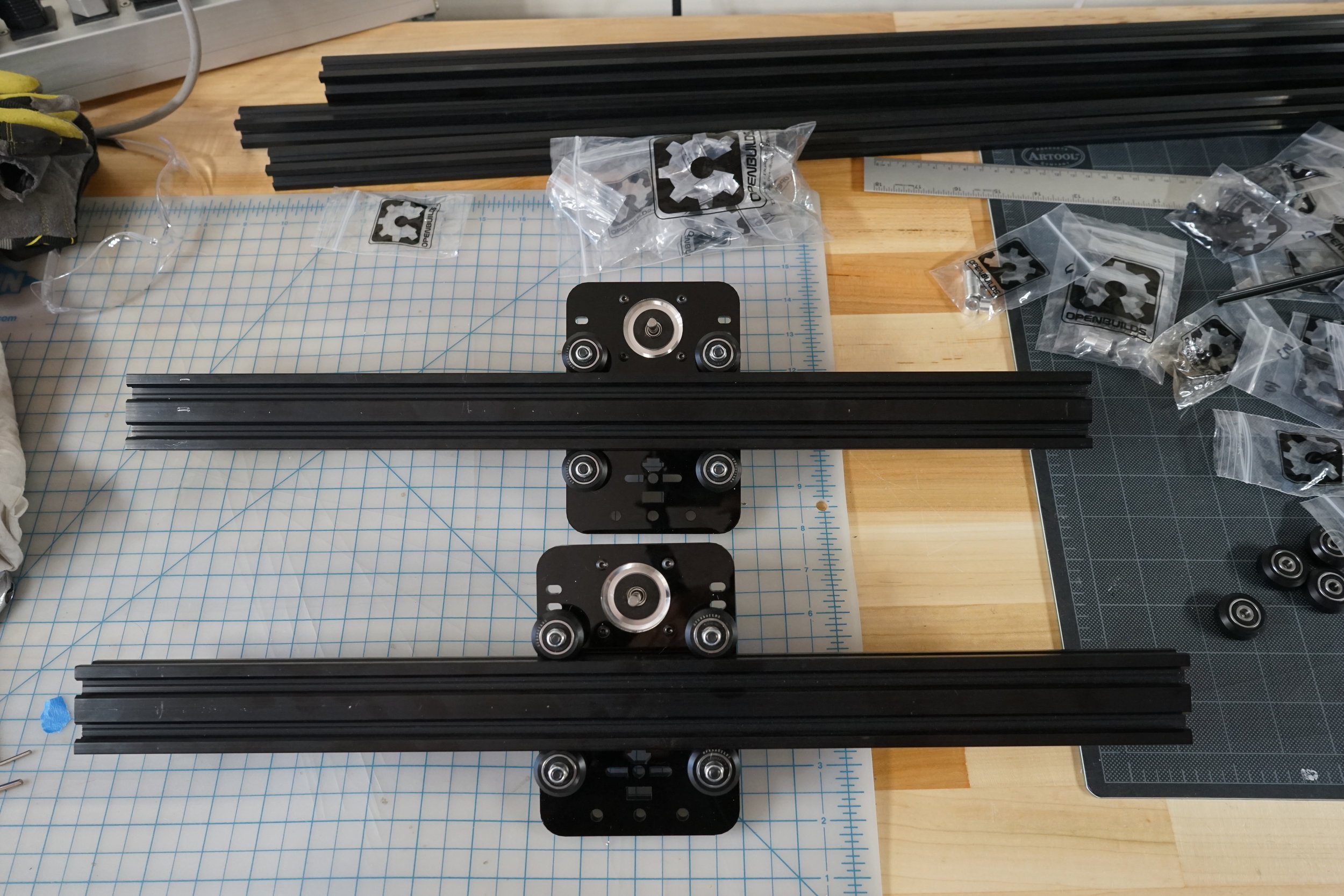
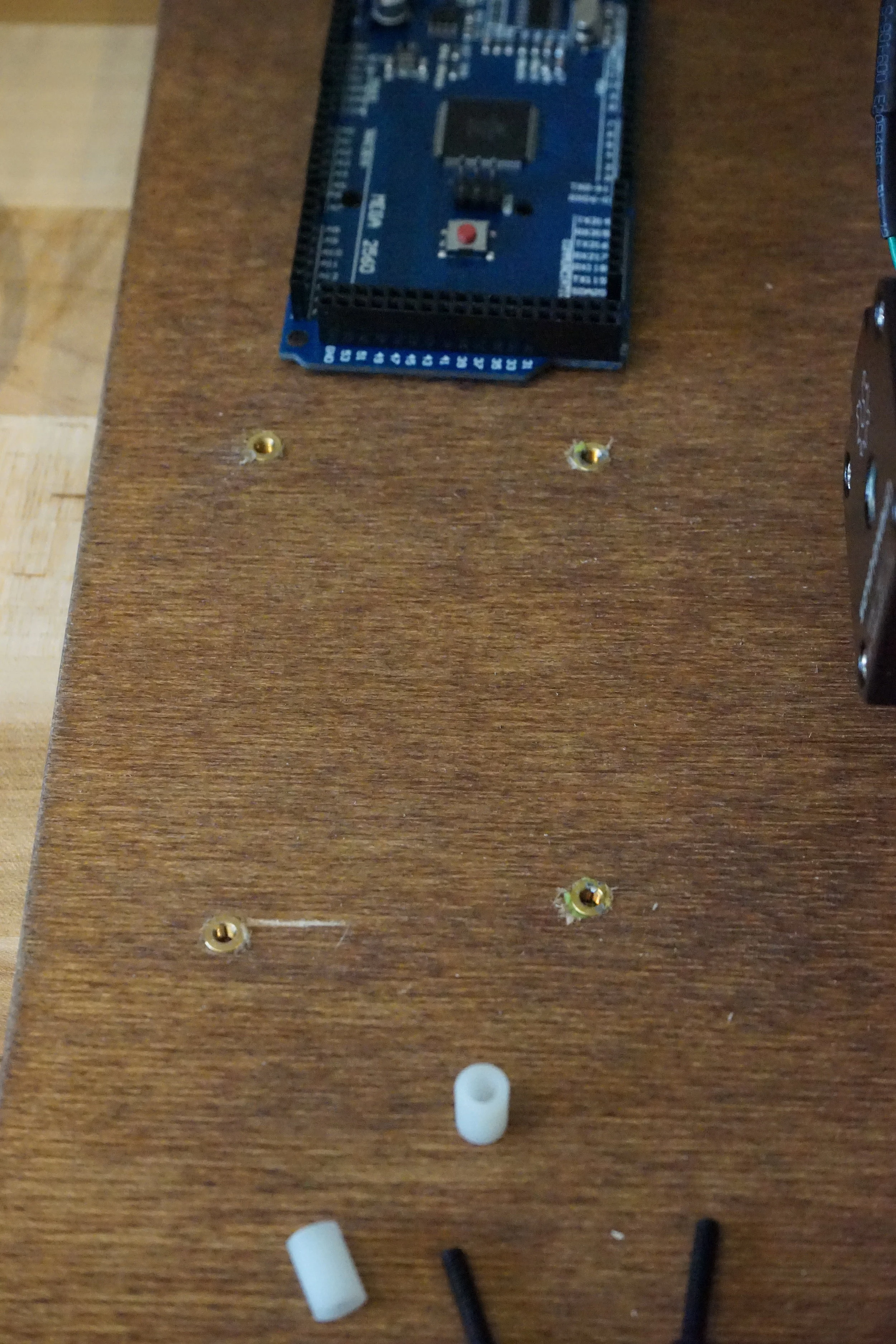
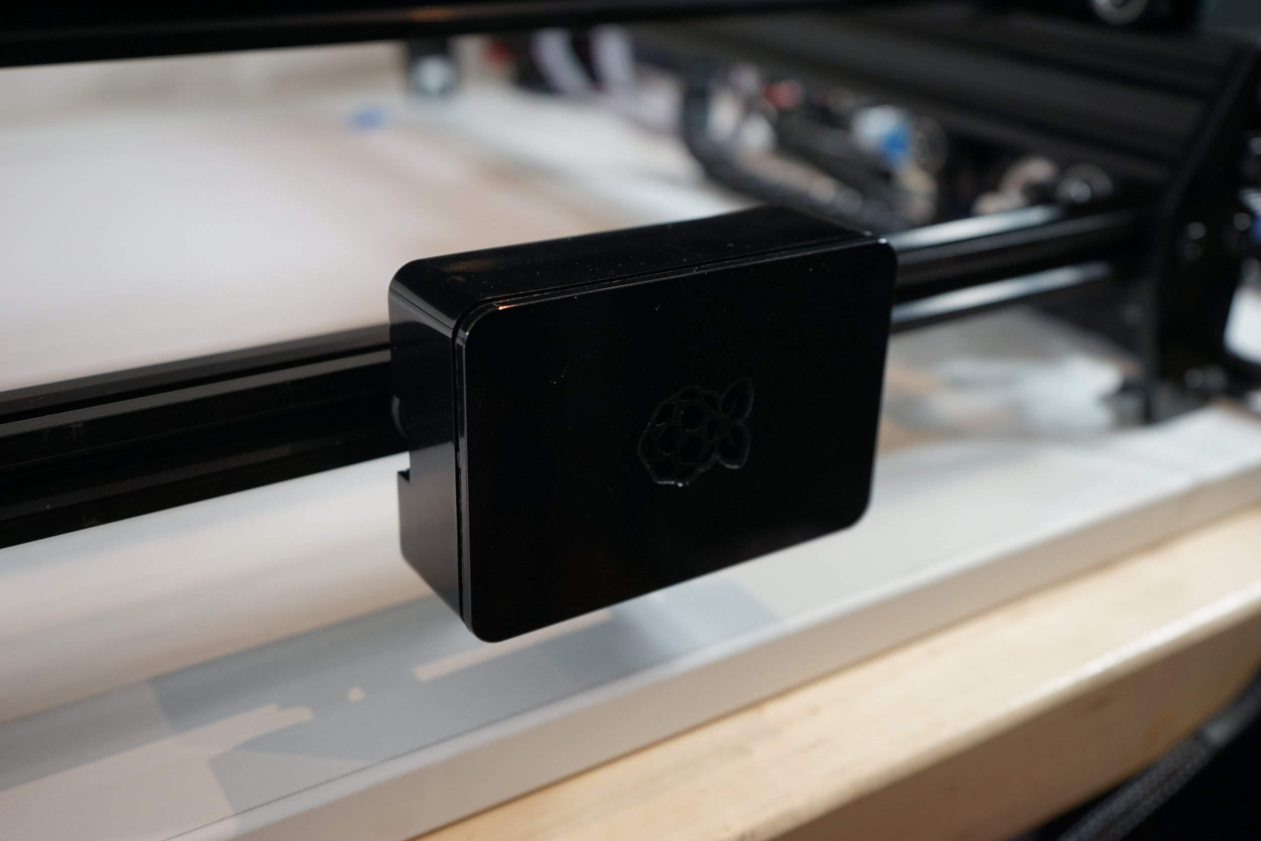
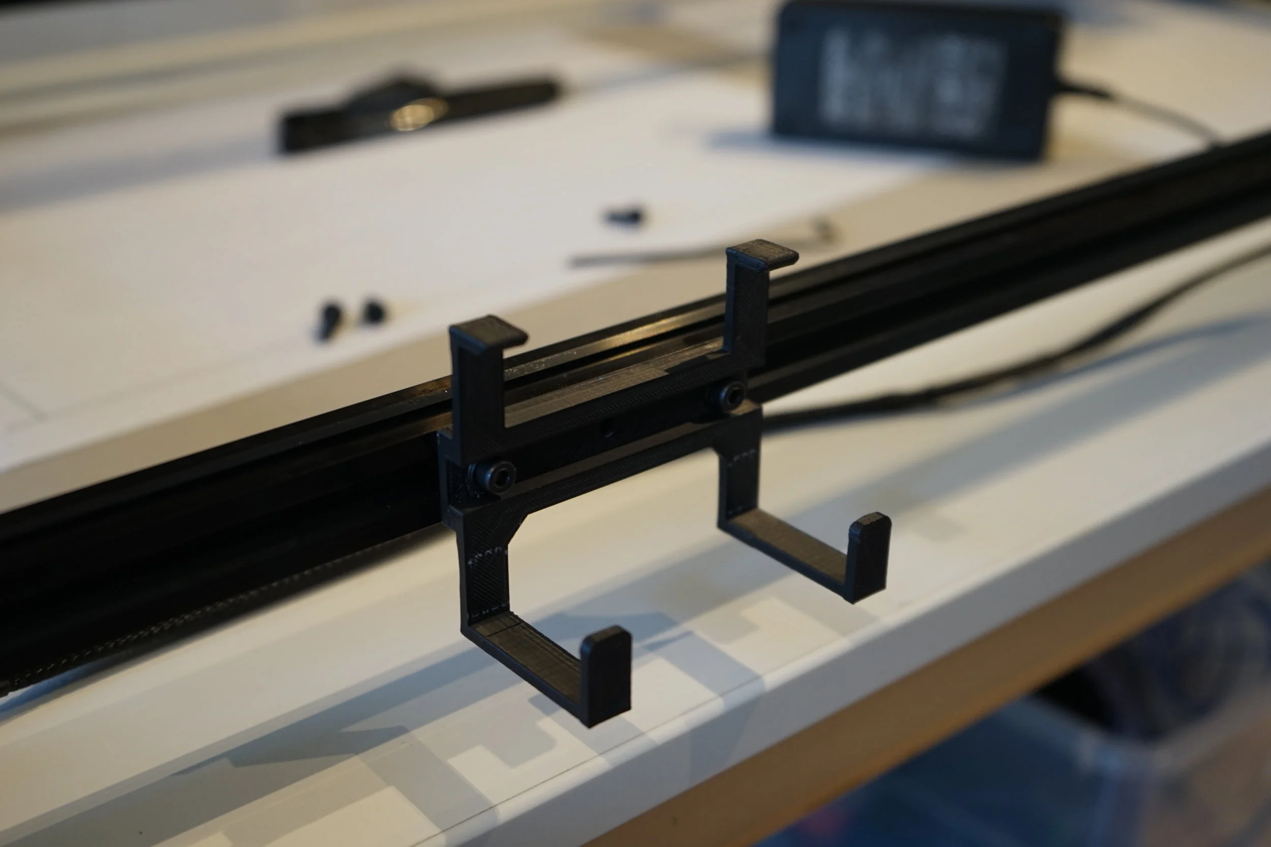
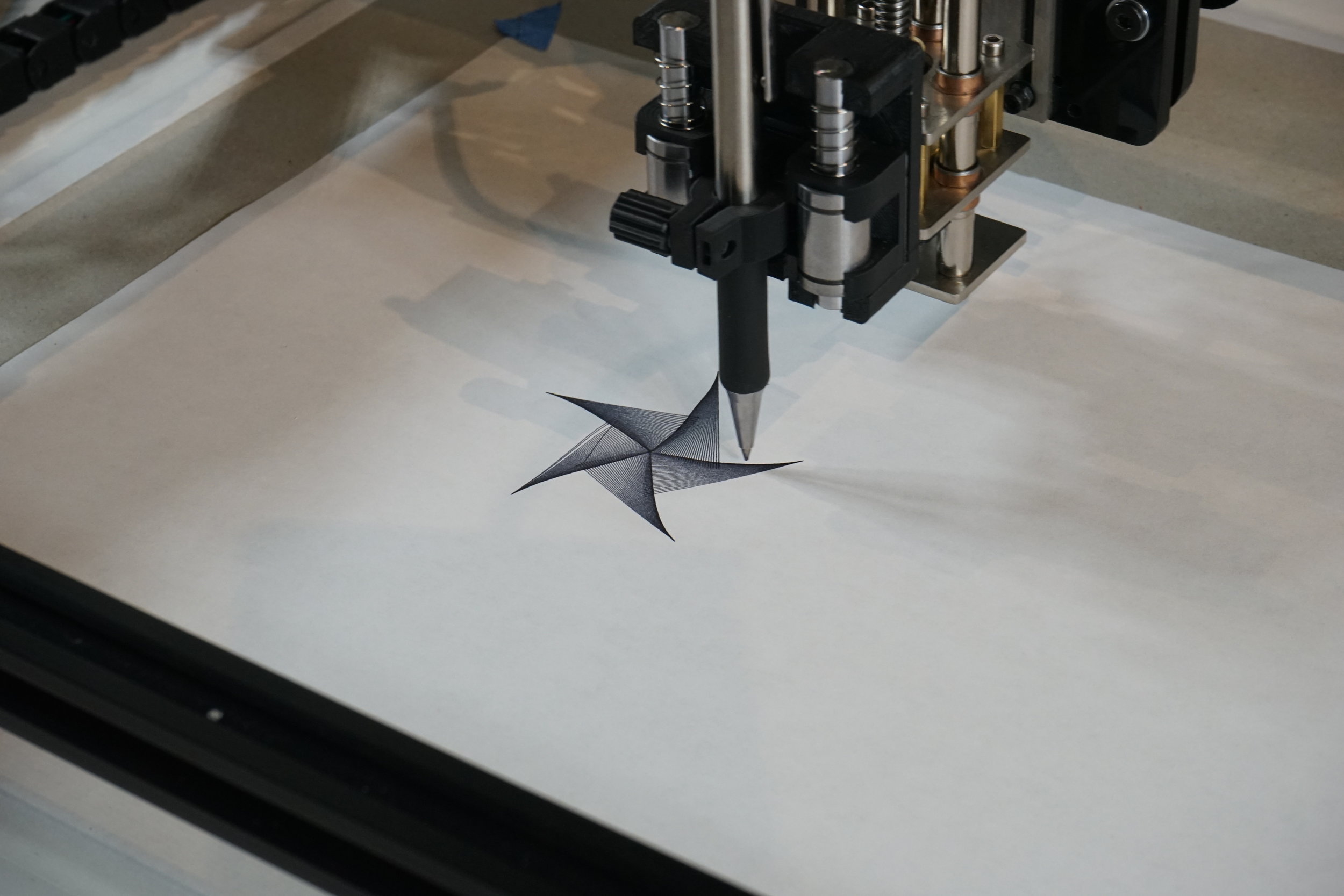
building a CNC pen plotter - process images and video. foundation is the ACRO System from Open Builds. additional components sourced from Amazon. some component designs derived from generous open-source DIY community (see below). everything else designed and 3D printed by me.

The foundation of the plotter is an ACRO System frame from Open Builds. It looks like this when it arrives.


Before assembling the frame it’s always a good idea to make sure your electronics, motors and firmware are all getting along. These images show the components that make motion possible - controller, motors, display, end-stop switches and wiring - all connected and being tested.

ramps test 01

The entire RAMPS setup (excluding limit switches) was about $45 on Amazon. This included an arduino clone, RAMPS shield, graphic display and 5 motor controllers.

For the Z axis I chose this part. It’s definitely overkill for just lifting a pen up and down, but I’m future-proofing for when I want to convert this thing into a laser engraver/cutter someday.


ramps motor test 01
everything works! still need to calibrate the stepping motor controllers though… (the motor labeled ‘z’ is actually Y2 - the ACRO System uses a 2 motor Y axis design)

The ACRO System frame assembly begins with wheels. Lots of them. To move the X and Y axis gantries around.


Wheels installed on the slick laser cut acrylic motor mounting plates. These are for the dual Y axis motors.

Motor mounts sliding smooth on their aluminum extrusion rails.


Y axis rails with the drive belts installed.


X axis motor mount assembly complete.

Basic frame assembly complete. This thing is all aluminum and acrylic. Not the sturdiest CNC framework in the world but all I am going to ask it to do is drag a pen nib across some paper.

Now for the Z axis. This came pre-assembled with the motor and wiring for $66. Let’s hear it for free trade.

Attaching the ACRO System acrylic mounting plate. Later I will fabricate a pen holder for this.

The Z axis connects to the X axis…

Couldn’t help myself at this point. Had to do a blue tape pen mount operational test.

Pretty good! Some definite wigglyness to the linework - I think it is the result of the inertial forces of this heavy Z axis being jerked around on this lightweight aluminum X-Y framework. Also the surface isn’t entirely level so the pen didn’t mark the surface in some places. Ah well…stuff to deal with later.

Endstop switches allow the CNC control system to ‘know’ where its X, Y and Z axes are located in space. I designed some super simple mounts in Solidworks and printed them in black ABS. This shows the Z axis mount.


